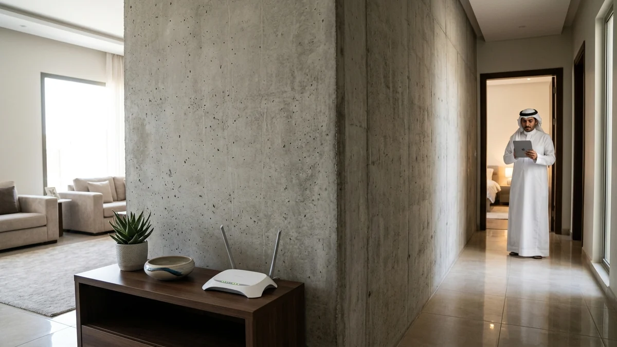
- The Diagnostic Walk Test: Measuring RSSI in dBm and Mapping Household Dead Zones
- Architectural Attenuation Physics: How Concrete, Mirrors, and Metal Cabinets Absorb RF Energy
- Zero-Cost Remediation First: Five Configuration and Placement Fixes Before Buying Hardware
- Repurposing Hidden Wall Conduits: Activating Dormant RJ45, Telephone, and Coaxial Runs
- Spatial Node Geometry: Precision Placement Rules for Upstairs Bedrooms, Majlis, and Annexes
- Frequently Asked Questions About Eliminating Home Wi-Fi Dead Zones
- Why does my phone show three Wi-Fi bars in the bedroom when web pages refuse to load?
- Does narrowing 5 GHz channel width from 160 MHz to 80 MHz or 40 MHz extend room reach?
- Why do bathrooms and kitchens positioned along a hallway block Wi-Fi into the back bedroom?
- How should external router antennas be angled to cover both ground and upper floors?
To permanently eliminate a bedroom or majlis Wi-Fi dead zone, you must follow a systematic four-stage engineering sequence: map the exact signal drop-off in decibel-milliwatts (dBm) using a walk test, remove immediate physical and metallic obstructions choking your main router, tune radio channel widths to maximize spectral power density, and—when concrete attenuation exceeds single-router physics—deploy an access point or Mesh node anchored at the -60 dBm midpoint or connected via existing wall cabling. In well over half of Saudi apartments and villas inspected for weak bedroom coverage, the dead zone is artificially created by locking the fiber gateway inside a recessed metal hallway distribution box, routing the signal path diagonally through a tiled bathroom wall, or leaving the 5 GHz band on an overly wide 160 MHz channel that collapses under thermal noise at long range. Correcting placement, spectrum settings, and dormant wall jacks resolves most dead spots before you ever need to purchase new networking hardware.
When a newly activated high-speed connection from FiberHub's residential fiber plans delivers blazing gigabit speeds in the living room yet drops to an unusable crawl behind the bedroom door, the bottleneck lies entirely within indoor radio frequency (RF) propagation physics rather than your external fiber line. High-frequency microwave signals do not curve smoothly around hallway corners; instead, they suffer cumulative absorption, reflection, and multipath scattering every time they encounter steel rebar, cement block, tinted glass, or ceramic tile. This step-by-step diagnostic and remediation guide walks you through measuring real signal metrics, executing zero-cost physical and RF optimizations, unlocking hidden in-wall cabling, and positioning nodes for 100% uniform household coverage.

The Diagnostic Walk Test: Measuring RSSI in dBm and Mapping Household Dead Zones
Relying on the three or four curved Wi-Fi bars at the top of a smartphone screen is the single biggest mistake homeowners make when troubleshooting dead zones. Visual signal bars have no standardized calibration across device manufacturers, update sluggishly, and completely hide co-channel interference and background noise. To diagnose a dead zone with engineering precision, you must measure the Received Signal Strength Indicator (RSSI) in dBm (a logarithmic scale running in negative numbers from -30 dBm down to -90 dBm, where every 3 dB drop represents a 50% loss in received radio power) alongside the Signal-to-Noise Ratio (SNR):
-30 dBmto-50 dBm(Peak Near-Field Zone): Typical within the same room as the primary router with clear line of sight. Devices negotiate their highest possible Modulation and Coding Scheme (MCS) rates, achieving full multi-gigabit plan speeds and minimal latency.-51 dBmto-65 dBm(Reliable High-Performance Coverage): The target design window for bedrooms, home offices, and family rooms. Supports uninterrupted4Kstreaming, competitive online gaming, large file transfers, and crystal-clear video calls with anSNRcomfortably above25 dB.-67 dBmto-70 dBm(The VoIP and Interactive Threshold): Wireless engineering standards established around IEEE 802.11 specifications recognize-67 dBmas the strict minimum boundary for reliable voice-over-Wi-Fi (Wi-Fi Calling), low-jitter video conferencing, and seamless roaming handoffs. Below-70 dBm, packet error rates climb and radios aggressively step down link speeds.-71 dBmto-79 dBm(The Unstable Fringe Zone): Phones still display one or two bars and remain associated with the network, but TCP retransmissions surge, web pages stall halfway through loading, and uplink transmissions from the phone's tiny internal antenna frequently fail to reach the router.-80 dBmand Weaker (True RF Dead Zone): Received signal power approaches the ambient electromagnetic noise floor (-90 dBmto-95 dBm), resulting in constant disconnections, authentication timeouts, and "Connected without Internet" errors.
To map your home without expensive enterprise tools, install Wi-Fi SweetSpots or enable the built-in Wi-Fi scanner inside AirPort Utility on iOS, use WiFi Analyzer on Android, or hold down the Option key while clicking the Wi-Fi icon on a macOS laptop to read live RSSI and Noise values. Start standing two meters from your router, then walk slowly down the corridor into the problem bedroom, recording the exact dBm reading at the hallway entrance, the bedroom doorway, the bed, and the far corner desk. You will pinpoint the exact structural barrier where the signal plunges across the -67 dBm cliff.
Architectural Attenuation Physics: How Concrete, Mirrors, and Metal Cabinets Absorb RF Energy
Radio waves in the 2.4 GHz, 5 GHz, and 6 GHz unlicensed bands lose energy both across open air (Free-Space Path Loss) and whenever they pass through solid matter. Because higher frequencies have shorter wavelengths (12.5 cm at 2.4 GHz versus 5.5 cm at 5 GHz), the high-speed 5 GHz and 6 GHz bands suffer significantly steeper attenuation through dense Saudi building materials than 2.4 GHz. The table below quantifies the real-world decibel loss incurred across common residential obstacles:
| Household Structural or Interior Obstacle | 2.4 GHz Signal Loss (dB) |
5 GHz / 6 GHz Signal Loss (dB) |
Underlying Physical Mechanism |
|---|---|---|---|
| Interior Gypsum Drywall Partition | 3 dB to 4 dB |
4 dB to 6 dB |
Low density; passes RF energy with minor loss |
| Solid Hardwood Bedroom Door | 4 dB to 6 dB |
6 dB to 9 dB |
Higher attenuation if fitted with acoustic core |
| Plastered Cement Block Wall (15–20 cm) | 8 dB to 12 dB |
12 dB to 18 dB |
Dense mortar and aggregate scatter short wavelengths |
| Ceramic / Porcelain Bathroom & Kitchen Wall | 10 dB to 14 dB |
15 dB to 22 dB |
Glazed tile plus water-filled pipes absorb microwave RF |
| Double-Glazed Low-E Tinted Thermal Glass | 12 dB to 15 dB |
18 dB to 25 dB |
Microscopic metallic oxide coating reflects radio waves |
| Steel-Reinforced Concrete Slab / Pillar | 15 dB to 20 dB |
22 dB to 32 dB |
Internal steel rebar grid acts as an RF shield |
| Large Wall Mirror or Recessed Metal DB Box | 20 dB to 30 dB+ |
25 dB to 40 dB+ |
Silvered mirror backing and sheet steel block transmission |
Furthermore, diagonal wall penetration silently multiplies these numbers. When your router sits in a corner of the living room and the signal travels at a sharp 30-degree angle through a 20-centimeter cement wall toward a down-hallway bedroom, the radio wave actually travels through more than 40 centimeters of solid masonry—often clipping a tiled bathroom or an elevator shaft along the way. Understanding this geometry explains why shifting a router just one meter sideways to align with an open doorway can recover 10 dB (a tenfold increase) of signal strength.
Zero-Cost Remediation First: Five Configuration and Placement Fixes Before Buying Hardware
Before spending money on new access points or Mesh kits, apply these five engineering adjustments to your existing setup. In many apartments and single-floor homes, these zero-cost fixes eliminate the dead zone outright:
1. Rescue the Fiber ONT/Router from the Recessed Metal Wall Cabinet:
Modern Saudi apartments and villas almost universally terminate the incoming fiber optic drop inside a flush-mounted steel communication box near the front entrance. Leaving your primary Wi-Fi router inside that closed metal enclosure traps your wireless signal inside a Faraday cage, destroying 20 dB to 30 dB of signal before it even enters the hallway. Either mount the router outside the metal cabinet on a nearby shelf using a short Cat6 patch cord, or leave the ONT inside the cabinet strictly as a wired modem and connect a dedicated primary router out in the open living space.
2. Enforce the 1.2-to-1.5 Meter Elevation and Clearance Rule:
Placing a router on the floor, wedged behind a wall-mounted flat-screen television (which contains a massive sheet-metal electromagnetic shield), or tucked inside a closed wooden media console chokes near-field radiation. Elevate the router onto an open shelf or table 1.2 m to 1.5 m above the floor, maintaining at least 40 centimeters of clear air away from metal appliances, aquariums, and cordless phone bases.
3. Optimize Corridor Line-of-Sight Geometry: Stand at the entrance of the bedroom hallway and look back toward the living room. If a concrete structural column or a bathroom wall blocks your visual line of sight to the router, slide the router along its table or onto the opposite wall so it has a direct visual path down the hallway. Radio waves bounce efficiently down open corridors when given a clean entry angle.
4. Tune Channel Selection and Narrow Channel Widths for Range (20/40/80 MHz):
Leaving router radio settings on Auto frequently results in severe co-channel interference or overly wide channels that fail at long distance:
- On
2.4 GHz: Lock the channel manually to1,6, or11(the only three non-overlapping channels) and force Channel Width to20 MHz. Using40 MHzon2.4 GHzoverlaps neighboring networks and triggers constant collision backoffs. - On
5 GHz: Many modern routers default to160 MHzchannel width. While160 MHzdelivers peak speed two meters away from the router, every doubling of channel width doubles the thermal noise floor (+3 dBnoise penalty) and spreads transmit power thinner across the spectrum. Stepping your5 GHzchannel width down from160 MHzto80 MHz(or40 MHzin heavy concrete homes) immediately boosts effective Signal-to-Noise Ratio (SNR) by3 dBto6 dBin distant bedrooms, turning an unstable-76 dBmconnection into a rock-solid link. Also test clean UNII-1 (36–48), UNII-3 (149–161), or DFS channels where supported.
5. Calibrate Band Steering and Roaming Assist Thresholds:
If your router merges 2.4 GHz and 5 GHz under a single SSID (Smart Connect), a device in a far bedroom may cling to a barely usable -79 dBm signal on 5 GHz instead of dropping to a strong -64 dBm signal on 2.4 GHz. Either configure the router's RSSI Steering Threshold to kick clients off 5 GHz once they drop below -70 dBm, or split the bands into distinct network names so distant smart TVs and bedroom devices can lock onto the longer-reaching band when needed.

Separate indoor Wi-Fi bottlenecks from line capacity issues
If slow speeds or high ping persist over direct Ethernet, check whether fiber or a higher upload tier is available at your address.
Repurposing Hidden Wall Conduits: Activating Dormant RJ45, Telephone, and Coaxial Runs
When physical distance and multiple reinforced concrete walls exceed what a single router can penetrate (because client transmit power and regional Effective Isotropic Radiated Power EIRP limits are capped by regulations), the most reliable way to feed a distant room is through a physical wire already hidden inside your walls:
- Patching Unconnected
RJ45Wall Data Ports: Many Saudi homes built in the last decade featureCat6data sockets in every bedroom that appear "dead" simply because the far ends of those cables are hanging loose inside the hallway distribution cabinet. Installing an inexpensive 5-port or 8-port Gigabit Ethernet switch inside the distribution cabinet and plugging those room cables into the switch ports activates live gigabit wired ports in every bedroom within minutes. - Converting
RJ11Telephone Wall Jacks into Gigabit Ethernet: Inspect the telephone wall sockets (RJ11) in your bedrooms by unscrewing the faceplate. In a vast number of Saudi villas and apartments, electrical contractors pulled standard 8-wireCat5eorCat6network cable through the telephone conduits, using only two wires (blue/white-blue) for the landline jack and wrapping the remaining six wires behind the plate. If those cables run point-to-point back to the main distribution box (rather than being daisy-chained room to room), you can crimp standardRJ45keystone jacks onto both ends and instantly gain a dedicated1 GbpsEthernet backbone into the dead bedroom at virtually zero cost. - Deploying MoCA 2.5 Adapters Over Existing Coaxial TV Cables: If your home has no Ethernet cabling and telephone conduits are blocked, check for coaxial satellite TV outlets (
RG6). Multimedia over Coax Alliance (MoCA 2.5) adapters convert existing coaxial wall wiring into a shielded2.5 Gbpsnetwork backbone with under3 mslatency. Unlike Powerline Ethernet adapters—which suffer severe throughput drops across Saudi three-phase electrical breaker panels and high-load air conditioning circuits—coaxial cable is heavily shielded and immune to electrical appliance noise.
Spatial Node Geometry: Precision Placement Rules for Upstairs Bedrooms, Majlis, and Annexes
When adding a secondary Mesh node or wired Wireless Access Point (WAP) to eliminate a persistent dead zone, spatial geometry dictates performance. Follow these four placement rules aligned with best practices from the Wi-Fi Alliance:
- The Midpoint Rule for Wireless Nodes (Never Place Inside the Dead Zone): If you are adding a wireless Mesh satellite node without a wired backhaul, do not place the new node inside the dead bedroom. A node placed where signal strength is
-80 dBmhas no viable upstream connection to relay. Instead, use your walk-test app to find the hallway or landing midpoint where the signal from the main router measures between-60 dBmand-65 dBm, and place the satellite node there so it bridges strong signal across the final wall into the bedroom. - Stairwell Vertical Alignment for Multi-Story Villas: Rather than forcing wireless backhaul signals straight up through a 30-centimeter steel-reinforced Hordi concrete floor slab, place your ground-floor node within sight of the central staircase and position the upstairs node on the first-floor landing overlooking that same open stairwell shaft. The open air column acts as a low-loss vertical waveguide between floors.
- Direct In-Room Termination for Wired Access Points: Conversely, when connecting a secondary access point or Mesh node via Wired Ethernet Backhaul (or optical FTTR), the midpoint rule no longer applies! Because the cable carries 100% of the speed without loss, install the wired node directly inside the target bedroom, home office, or majlis where your devices actually operate.
- Dedicated Outdoor/Annex Links for the External Majlis (Mashab): Exterior villa walls combine double cement block, thermal insulation foam, and Low-E reflective glass, attenuating indoor Wi-Fi by more than
35 dB. Never rely on an indoor living room router to cover a detached courtyard majlis or driver's room; always run an outdoor-ratedCat6or fiber cable through the garden conduit and mount a dedicated access point inside the annex.
If your walk test reveals that even devices standing right next to the main router struggle when multiple family members stream or game simultaneously, your bottleneck is WAN bandwidth rather than indoor RF loss. Check available high-capacity fiber tiers at your building via the FiberHub coverage verification map, compare ISP speeds side-by-side on the broadband comparison matrix, or select an upgraded package directly on the residential fiber plans page backed by quality-of-service benchmarks enforced by the Communications, Space and Technology Commission (CST).
Frequently Asked Questions About Eliminating Home Wi-Fi Dead Zones
Why does my phone show three Wi-Fi bars in the bedroom when web pages refuse to load?
This classic symptom is caused by Link Power Asymmetry between your router and your mobile phone. A mains-powered home router transmits radio signals using high-gain antennas and amplifiers rated between 200 mW and 1,000 mW (within regional regulatory limits), allowing its downstream beacon frames to punch through two concrete walls and light up the Wi-Fi indicator on your phone. However, your smartphone relies on a tiny internal antenna powered by a battery-saving transmitter operating at just 15 mW to 30 mW. Your phone can "hear" the router shouting from the living room, but the router cannot hear your phone whispering back—so TCP acknowledgments and DNS requests fail to complete.
Does your current plan support your device count and upload needs?
Compare download/upload ratios and Wi-Fi 6 or FTTR hardware options across plans available at your address.
Does narrowing 5 GHz channel width from 160 MHz to 80 MHz or 40 MHz extend room reach?
Yes—narrowing channel width is one of the most effective RF engineering adjustments for extending usable range through concrete walls. Whenever you double channel width (for example, from 40 MHz to 80 MHz, or 80 MHz to 160 MHz), the router spreads its fixed transmit power across twice as much spectrum while the receiver lets in twice as much background thermal noise, reducing your effective Signal-to-Noise Ratio (SNR) by 3 dB per step. By narrowing the 5 GHz channel width from 160 MHz down to 80 MHz or 40 MHz, you concentrate spectral power density and gain up to +6 dB of link margin, allowing distant bedrooms to maintain a stable, zero-packet-loss connection.
Why do bathrooms and kitchens positioned along a hallway block Wi-Fi into the back bedroom?
Bathrooms and kitchens act as dense radio-frequency shields inside residential floor plans because they concentrate four high-attenuation materials into a tight space: thick glazed ceramic or porcelain wall tiles, galvanized steel or copper water supply pipes inside the walls, large silver-backed vanity mirrors (which reflect microwave signals nearly 100%), and heavy sheet-metal appliances like refrigerators and ovens. Additionally, water molecules naturally absorb electromagnetic energy around the 2.4 GHz band. Repositioning your router or adding a hallway node so the signal path skirts around the bathroom core rather than cutting through it dramatically improves back-bedroom reception.
How should external router antennas be angled to cover both ground and upper floors?
Standard external router dipole antennas radiate Wi-Fi energy outward in a flattened horizontal torus (doughnut shape) perpendicular to the antenna shaft, with a radiation null pointing straight out of the tip. In a single-floor apartment, all antennas should stand strictly vertical (90 degrees) so the horizontal signal plane spreads evenly across every room on that level. In a two-story duplex or villa where you want a single router to reach both the same floor and the bedroom directly upstairs, position half of the antennas vertically and angle the remaining antennas at 45 degrees (or horizontally) to tilt part of the radiation lobe vertically through the ceiling.
Completed tuning and ready for a more stable fiber line?
Check fiber availability at your address and compare low-latency plans for gaming, telework, and multi-floor homes.
Editorial Transparency & Neutrality Notice:
This guide is provided for comparison and decision support. It does not constitute final address coverage confirmation, binding operator pricing, or regulatory accreditation. Always verify final plan terms and box readiness before completing your subscription request.